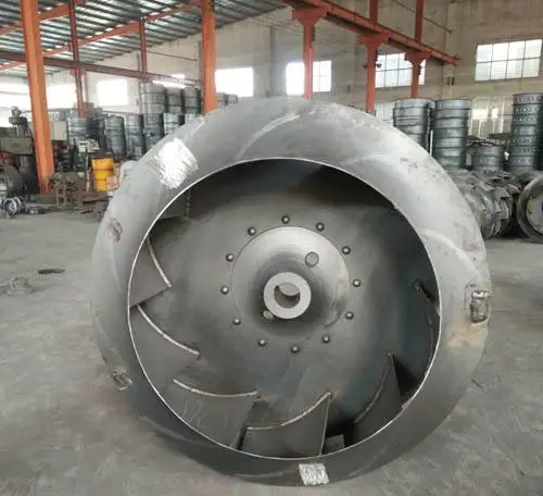
Literature review has revealed that a few literatures are available on three dimensional numerical analysis of a centrifugal fan/blower. More and more experimental research work is available in the field of turbo machine design and its evaluation. Turbo machines comprise various types of fans, blowers, compressors, pumps, turbines etc. The conversion is done through the dynamic interaction between a continuously flowing fluid and rotating machine component. Next month we will look into the advantages and common application of each of these designs.The turbo machine is an energy conversion device which converts mechanical energy to kinetic/pressure energy or vice versa. I hope these short descriptions help clarify the terms “closed”, “open” and “recessed”. The picture below is a good representation of the impeller, and the section view beside it illustrates the impeller location within the pump.

In fact, finer blades increase efficiency and are therefore often deemed more desirable. With the vanes basically out of the normal flow path, erosion is minimized and the vanes do not need to be as thick as they have to with other impeller styles. The coupling then spins the slurry within the casing, thereby creating the centrifugal force required to create discharge pressure. Instead of accelerating liquid down the vanes, these impellers use the vanes to create a hydraulic coupling. Often called “ torque flow” impellers, they create a centrifugal force in a unique manner. The third and slightly less common slurry impeller is the recessed impeller. In the absence of a front impeller shroud, the front wear plate completes the tunnel used to accelerate the slurry within the pump. The vanes of a semi open impeller are supported by a back shroud only and the impeller is completely void of a front shroud. The one major difference is the absence of the front shroud.

The semi open impeller is very similar in its design to the closed impeller. The two images below illustrate this design. In this design, the liquid follows a path down a tunnel formed on the sides by the vanes and is “ closed” in on the top and bottom (or front and back depending on shaft orientation) by two shrouds. The first, and arguably the most, rugged design is the closed impeller. So here it is.Īlthough there are numerous styles/designs offered by pump manufacturers, most slurry pump offerings boil down to a variation of one of two basic designs, with a third design, slightly less common, that is becoming more widely used every year. I recently received an e-mail asking to explain what the terms “open” or “closed” referred to when discussing impellers in a slurry pump.


 0 kommentar(er)
